Topics Covered
This topic is all about the basics of Networking. It’s less of a practical lab exercise you can do, like the previous topics, and more about laying the groundwork + help you with actual network troubleshooting. (It’s a LONG one, so yeah, do take your time XD)
The things that I will be sharing on here are for the most part, just an overview on the subject, so feel free to read more about each sub-topics if you need more help. The goal of this Networking Overview is to give you have a good idea on how Networking works, and how to do some basic Network troubleshooting using the tools I will be giving here.
Without further ado, here’s the list of Things I will be talking about:
- Explain the components of things in networking settings when you do an “ipconfig /all” in CMD on Windows >IP, Subnet, Gateway, DNS, DHCP, etc..
- Next is to talk about some basic network hardware. Routers, Switch, Firewall, Access Point, Wireless Lan Controller, Patch Panel, Ethernet cable (Cat 5e and 6+), Fiber (No VOIP Phones cus we on Microsoft Teams now, and that’s more with Telecom stuff, not necessarily Networking).
- Then Some common thingies you will need to know > LAN, WAN, VLAN.
- Then a really important thingy which will probably be covered a bit more later > Subnet Overview > Will only talk about /24 for this overview.
- Then a basic you need to know > OSI Model.
- Lastly, I will be showing you how these thingies works together and some basic Network troubleshoot tips to give you a bit of an idea on how to apply these stuff for real work stuff.
- There are some important potato drawings toward the end as well. These not real, but usable Network Topology that’s gonna help you visualize the way Networking works.
Components of ipconfig /all in Windows CMD. I want to start with something familiar to kinda ease you into it…

>the command “ipconfig /all” in windows Command Prompt is to get all the relevant network settings on the computer.
These are the things you mostly care about when configuring network or when you’re troubleshooting a network related problem.
- Adapter > this is basically where you get your Network access from (like a network port, but not quite). If your PC has multiple ethernet port, or have wifi, then there can be multiple options here. (You can usually tell what the computer is connected to with this info here -in this case, the server Nyght-DC1 (host name at top), is connected via Ethernet 2, and description will often tell you the speed it can do.
- The Physical Address is the MAC address of the Adapter > It’s written in Hexadecimal ex:08-00-27-7D-26-9B (12 Hexa = 48 bits). This is used as an unique identifier for the device, and you will need this when looking at the MAC Table of a switch for troubleshooting stuff. (fyi, you can use this MAC to identify the vendor for the device > good when you troubleshoot stuff. You can check if a device is a Switch, or some random smart bulb lol).
- DHCP, like we saw from the previous topic, is basically the service that leases IP to your devices.
- DNS, again from last topic, is the service that converts a name into an IP and vice versa.
- IPV4 and IPV6 > IPV4 is the old standard of Internet Protocol, and though ‘old’, it’s still the one you’ll probably be working with for internal routing and stuff (it’s the usual 192.168.69.1). IPV6 on the other hand is the new dude which is to replace the old ipv4, but you probably won’t be working with it (it’s 128 bits! >it’s also written in Hexadecimal ex: 2001:0db8:85a3:0000:0000:8a2e:0370:7334 and it’s a pain to work with if you manually config XD) -either way, when you work with these, you gotta always use the calculator to convert them to regular decimals or Binary ;-; > It makes your life much easier when working with IP and doing subnet stuff.. I mean there are some websites as well :3

- Subnet > Just as the name implies, it’s a Sub Network. That means that it’s a smaller network inside a larger network. You can split a larger network, into multiple smaller sub-network. (More on this later). But quick example > -you can get 256 different /24 subnets from a /16 Network. (Subnet also means just a Network, depending on the context)
- Subnet Mask > This is what determines the size of a Subnet/Network. For example, a subnet of 255.255.0.0 or /16 (in CIDR notation) means that there are 65,534 possible Addresses you can use for your host devices (which is a lot of addresses, so you would usually split this into multiple, smaller subnets) And the regular 255.255.255.0 (or /24) Subnet has 254 usable address you can assign to your hosts (PC and stuff)
- Default Gateway > This is the default route that the network traffic (IP packets) will take if there are no destination found on the current Subnet. For your small office and home network, this will be the ISP Router, which will forward all the traffic it gets to the internet. Like when you access your emails, or watch youtube, pretty much anything you do online goes through the gateway (gateway to za worldo!).
- You don’t need to worry about NetBIOS since it’s only for legacy stuff (aka, really really old and should not be in use)
- Tcpip > The Internet protocol suite, commonly known as TCP/IP, is a framework for organizing the set of communication protocols used in the Internet and similar computer networks according to functional criteria (wiki). Really just trivia knowledge. (the TCP protocol on the other hand, is something more interesting, but not something you gotta worry about for now).
Overview of Typical Network hardware + picture so you see what they look like (I will explain how these things work together later)
- Router > The one you are mostly familiar with, the router you got from your ISP (Internet Service Provider), is actually not just a router. Not only is it a router, it’s also a Switch, a Firewall, (Sometimes a Modem -that convert stuff into ethernet), an Access Point and a goddamn footrest if placed in the right spot!
-Jokes aside, a Router is a device that routes (forward) network traffic across different network. They can do a bunch of stuff too, but essentially, a router’s main job is to route Network traffic (called Packets -See OSI model much further down) from one network to another. Routers works with IP Addresses when doing this (as opposed to Switches, which works with Mac Addresses).

> The photo bellow is photo of an old Cisco Router. These are the thingy that are used in enterprises (well not this particular one, it’s been out of support for a long while XD). There are also various config for these, but you mostly know it’s a router when there’s not a lot of Ports at the back of it (as opposed to Switches).
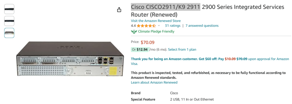
- Switch > There are 2 kinds of Switches, Regular, or L2 Switch and L3 Switch. The L2 and L3 refers to their capabilities. Switches moves traffic using Mac Address (physical address) as their destination. They transport traffic (called Frames) across one Network/VLAN. L2 Switches (regular Switch) can only move traffic on the same VLAN and needs a Router to help them move traffic between VLANs, But L3, or Multilayer Switches, can do L2 Switch stuff + move traffic across different Network, and VLANs. They are essentially a Router + Switch combo.

- A Firewall, like the Fortinet thingy bellow, is a device that monitor and filter traffic (well, they can also do other stuff, but this is their main job). You can allow and block specific traffic and some other security stuff. Firewalls usually are also Routers and other stuff, but their main job is to monitor and filter network traffic. If you got one of those, some Firewalls also comes with a VPN access. This is typically what’s allowing you to work remote and still have access to resources on the Local Network at your job.

>The way Firewalls works is by allowing and denying protocols, ports and IPs to secure the Internal network. This ACL (Access Control List) thingy of doing stuff, can also be setup on a Router but it’s much easier to do on a Firewall which is dedicated for that purpose, and there’s other stuff it does as well. It looks like something like this (https://docs.fortinet.com/document/fortigate/6.4.0/new-features/815846/consolidated-ipv4-and-ipv6-policy-configuration)

FYI, the Firewall on your computer does this filtering and blocking stuff too btw for your computer! And sometimes, you gotta get in the Firewall config of a server to allow some stuff (Apps, Protocols, etc..). Pretty much the same way as in your typical Network Firewall!

- Access Point (AP) > The other really important thingy you need is an Access point. It’s the thingy that gives you wifi. At your house, your ISP Router has a built in Access Point, but in larger office, it’s a separate device. They can be managed by a WLC (Wireless Lan Controller), which can also be integrated into a router/stand alone thingy, or they’re managed some other ways, if not standalone.
>If your wifi coverage is bad, you can get yourself one of these AP dudes.. I myself plan on getting one set up when I have the time cus I’m the one having a bad time XD. The ones for business use looks and act pretty much the same as this guy btw. They’re mostly simple to work with (*mostly..) This might be a bit overkill for me, but I kinda really really “need” it XD.. (or I get some cheap router and have it on repeater mode -hmmmmm).

- Patch Panel > While not really a Networking device, you’ll definitely see these if you go in a Network closet. It can look like a switch at the front, but it’s really just a way to organize the cable spaghettis. You can tell it’s not a Switch, cus it got nothing at the back.

- Now about the cables > For most things you’ll be working with, you’re going to use an Ethernet Cable. The ones you’ll be using specifically are most likely going to be a Cat# cable. They are the typical cable you see at the back of the router at home or desktops at work. When buying one, working with stuff > Make sure the cable you use is at the very least a Cat5e cable (1Gbps. They have different specs, with wildly different speed but similar maximum length) Typically, higher number = better, but you really don’t need to go overboard lol. Cat 6 is good for most stuff.

>The newer Cat8 and stuff like that are a bit too much for most ppl lol. Just a regular cat6 is enough, same applies for most small companies and schools. You won’t be going over that 10Gps, and most businesses don’t even have Gigabit internet XD (which is where most traffic are directed to nowadays with the cloud and stuff). A Cat 6 cable definitely won’t be the bottleneck for most companies lol.


- For Fiber optic cable, You gonna need a Transceiver or connector at the end of it. This thingy is the one I worked with before -the cost is not too bad for this speed. The price for these varies A LOT depending on the cable spec, but mostly, depending on the connector/transceiver used. (Fiber can also run farther for some specs.. but yea, we don’t worry bout that for now, lol)

>Regardless of the specs of the shape of it, it’s just a cable lol. Just make sure you get the right cable with enough specs and connector and you good to go! (you most likely gonna be working with cat5e or cat6 cable most of the time anyway).
Now, let’s go over some common thingies you see/hear often in Networking.
- LAN > A local area network (LAN) is a computer network that interconnects computers within a limited area such as a residence, school, laboratory, university campus or office building (Wiki). It’s just the name for the Network at your home/work/school. If it’s one building, it’s a LAN. LAN can have multiple Subnets btw.
- WAN on the other hand is just a bunch of LAN connected together > A wide area network (WAN) is a telecommunications network that extends over a large geographic area. (wiki). A good example of this is the Network of a Multi Campus college -one in NYC, and one in NJ -the combo of those 2+ sites is a WAN.
- VLANs > Virtual LAN. It’s just a virtualized LAN. These are configured in the Switch settings to separate traffic and stuff. This is what differentiate an Switch, from just a cable connection (or a Hub, which are stuff you won’t be working with, so moving on). L2 Switch (regular SW), can add a layer of separation between device connection by putting them on different VLANs even though they might be physically connected together. Again, you need an L3 switch (or a Router) to be able to route between VLANs, since it’s basically like routing across different network (but not quite the same XD).
>An simple example you’ve all seen with this is the Guest Network at a coffee shop > That different SSID (Wifi ID/”name”) runs on a different VLAN or different Subnet altogether, depending on the config. That way, the network traffic can access different resources and be managed separately (in term of restrictions, priority, and whatever you want).
Subnet Overview > This is a HUGE topic on itself, but for now I will only talk about the basics to help you get started
To make things a lot simpler, I will only talk about /24 Subnet. 255.255.255.0 is the Decimal notation of /24 which is written in CIDR notation. They’re the same thing. and saying /24 is easier, lol. Also, I will only IPV4 cus IPV6 is a whole other beast (and you mostly won’t be working with it… but if you do, why are you reading this blog LOL)
>First, why would you need/want different Networks/Subnets in your environment. The main reasons for this is because is to conserve the addresses available on the network. The other reason is to separate traffics from different sources, just like how you would use VLANs. And it makes things easier since you don’t have to work on a huge network at once, but smaller parts at a time. I mean I’m sure there’s more reason, but it’s just cus it’s better is what I mean. (First reason shoulda been enough lol)
- Before we get started on the subnets, some stuff about the IP address itself. The IP you typically see on your devices (IPV4), is written in dotted decimal format, to make it easy to read and understand. But, when you’re subnetting and stuff, you have to convert it back to Binary to see the Bits (0 and 1) you gonna be cutting/changing. (forgot where I got the photo, RIP the sauce ;-;)

>You can see here that there are 32bits in an IPV4, they are paired in 8 > called octets. The CIDR notation that uses the Slash prefix (ex: /24) > indicates where in those 32 bits the slash/cutoff between the network and host address happens. In the case of the /24 subnet, the First 24 bits are part of the Network address and cannot be changed, and the 8 bits at the end are what you gonna use for the host address (IP you assign to your devices). Or you can also Cut off a /24 into smaller Subnets, cutting it into 2 /25 (each having 128 addresses)
>The picture bellow show how the thingy with IP address and Subnet mask binary thingy works > this is how we determine the number of Hosts address available and what the Network address is. (photo from https://www.fourfaith.com/industry-news/what-is-netmask.html)

- The way it works is > You put the Binary notation of an IPV4 address on TOP of the Binary notation of the Subnet mask. And then you do a bit of a logic gate thingy (I’ll spare the details lol) > Basically you compare the 1 and 0 from Subnet to the Host IP (Bottom to Top) > For every 1 on the Subnet mask, the output is the same as the Host (not changed), and for every 0 on the Subnet mask, the output is always 0.
- And what you get at the end (after converting back to Decimal), is the Network Address > 192.168.1.0 for the Network Above. And the 8 zeroes at the end (in binary format), represent the Host bits you can change > which gives you the 0-255 in Decimal format > which means, you can assign them (after removing the first and last lol), to your hosts devices.
>This makes no sense the first time you do it XD >Highly recommend watching more videos on Subnet like this one from NetworkChuck on YouTube (https://youtu.be/5WfiTHiU4x8?si=W8bwEUGbEpeRo2fB). You can also set any random IP (like 10.4.0.1) with 255.255.255.0 Subnet and then do the thingy to figure out the Range, Network address and so on (You can double check with an online calculator to see if you did it correctly). This thing is really simple once you get it down, I promise XD Just gotta do a couple practice runs…
The 1st IP on the Network is assigned to the gateway (typically, but it can be whatever IP you config), that’s why when you look at your Network config at home, it usually gives a gateway similar to 192.169.1.1 with a subnet mask of 255.255.255.0 (the easy /24)

>The reason why there’s 2 less IP for the Usable hosts, is because you need 1 IP for the Gateway (so your network can network with other network), and you also cannot use the last IP on your subnet, that is reserved for Broadcast. The Broadcast IP is used by a bunch of protocols and whatnot so you’ll break a lot of things if you assign it to a host (so don’t do it!)
(Got this cheat sheet here to help you with the conversion and stuff>https://www.pubconcierge.com/blog/subnetting-101-free-ipv4-cheat-sheet/) > There are many of these kinds of table online to help you get familiar with this whole subnet and CIDR notation thing, but starting with the /24 helps!

In the photo above, The IP Addresses is the number of Addresses there are in a given Subnet/The possible addresses you can give to the host devices you assign with this Subnet. The Subnet Mask, is used to indicate the size of network (You know it’s a small subnet if you don’t see any 0, and it’s huge when you see more than one 0 LOL). The Bits shown here indicate the number of Bits you can play with, either to assign to hosts, or for splitting into different Subnets.
- FYI, Calculator.net’s Subnet calculator (https://www.calculator.net/ip-subnet-calculator.html) is my favorite website for splitting subnets and figuring out configs of a certain network > It gives you all the info you need when working with IP stuff. BUUUT IT’S IMPORTANT TO LEARN THE BASICS BEFORE YOU USE THIS THING XD -watch some YouTube or read some articles on it.. > Only use this to double check your studies and stuff.. Or, you use it for troubleshooting at work cus nobody got time to deal with pen and paper at a client site lol…

The nice thing tho, is that most user facing network uses a /24 subnet, which you can tell stuff at a glance, so it saves you the hassle of needing the online calculator for troubleshooting network problems XD
But yeah, the Network Address from this IP Calculator thingy is what you gonna be using and comparing a lot between 2 hosts to check if they are on the Same Subnet, if they are not able to ping one another.
>Again, this is just an overview guide so you definitely gonna need more materials on this to get it down. It’s a bit tricky at first, but it gets simple when you get the idea of it. (Possible I make a Topic on this later to give you more materials and explanations… definitely took me a while to get too). Also there are Network classes, but you don’t really need to care about them, since we now use CIDR (Classless Inter-Domain Routing).
OSI + TCP/IP Model
>These thingies are used to visualize networking stuff and are especially usefully when it comes to going about troubleshooting a problem.
OSI Model and TCP/IP Model -They pretty much the same thingy, but OSI is the better one and the one you gonna be working with. You’re not going to be using the TCP/IP Model, but at least you know it exist lol…

>This OSI Model from (https://www.lifewire.com/osi-model-reference-guide-816289) is really cool btw. There’s also some cool stuff on their Blogs if you want to read (it’s a short one so it’s Nice) > The reason why the Data transported on each layer is called something different, is because there’s added info with the thingy, for routing the thing onto the different Layers. (Again, just cool trivia for you right now lol. You not gonna be troubleshooting with these or doing any analysis of the thingy > Honestly, I’d just ignore it for now lol)…

>Also some real good stuff here (https://community.fs.com/article/tcpip-vs-osi-whats-the-difference-between-the-two-models.html) >This whole article is really noice, highly recommend you read on it.
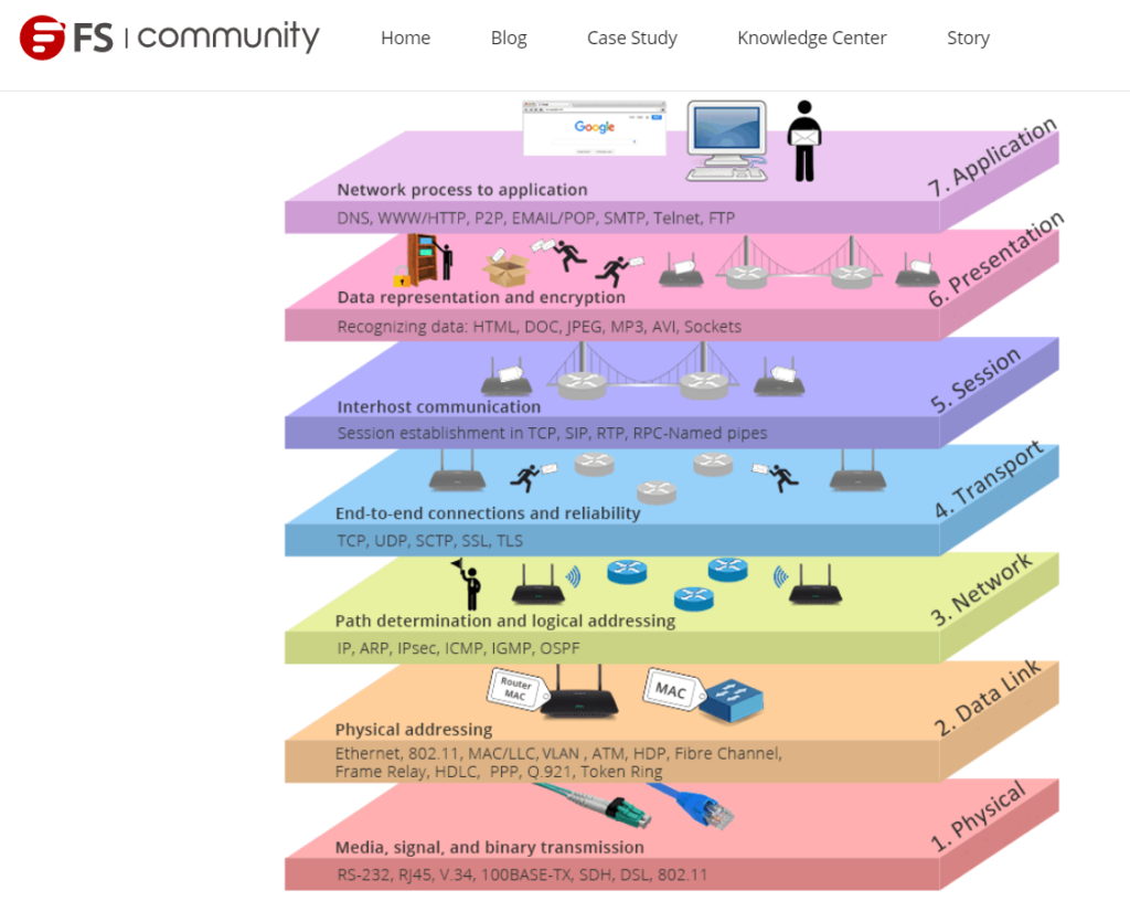
- The whole point I’m showing these OSI Models is just to give an overview, and that’s pretty much what this model is used for as well >For visualization of the Network thingy happening on each levels. You gonna be keeping this picture, especially this one above here, for when you’re doing Network troubleshoot (the difficult to figure out kind XD) > More on the Basic way top do this further down with the Troubleshooting Tips.
- Also, for most Basic Network troubleshoot > You’ll be dealing with Layer 1 to Layer 3 (cables, Mac Address Table, IP and Subnets). And then some Layer 7 (DHCP, DNS, or smthin’ like that).
Also, something I haven’t talked about, is Redundancy > It’s kind of a big deal for business use.
You always want to have a backup in case something goes down (double connection to a network + secondary routes, backup server, secondary ISP, hot standby router, you get the idea). But again, this is just an overview so just gonna mention that lol. (Might do a topic on this later -I wanna do secondary/backup windows server config as well… for routers and switches, it’s more straightforward and you can even stack ‘em up). But yeah, we don’t care bout any of that for now…
Putting Things together
That was a lot of info I gave you, and it might seem weird if I just leave it here, so I’ll do something to help you put things together. (AGAIN, JUST AN OVERVIEW!)
>Here’s a fun graphic to help you visualize stuff. It is not a realistic Network config, but it’s got the main ingredients so we going with it!
FYI, these kind of graphics (Network Topology) are used to represent these devices in an easy to understand way. IRL, these routers, firewall, switches and servers, are usually stacked on top of each other on the same rack. The VLANs and different Network config, are just ways to separate them virtually. And we draw them this way to make it easier to config and stuff.
We will be working more often with these kind of graphics (Hopefully not hand drawn but with Visio or something XD) lol. Getting yourself Familiar with these, and understanding things at a glance will be really helpful for doing config + modification or design of Network stuff in the Future (Looking at you ensld -that interesting looking salad)
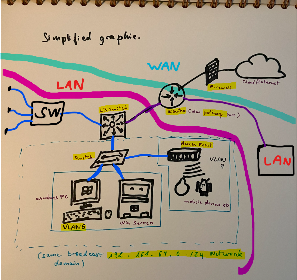
For this Topology, this is what the LAN area here would look like in person. (screenshot from https://www.networkingsignal.com/what-is-a-server-rack-detail-guide/https://www.networkingsignal.com/what-is-a-server-rack-detail-guide/) >It’s kind of a Homelab setup, but the smaller companies Network rack would have similar components inside their racks. (They might just use a full size rack).
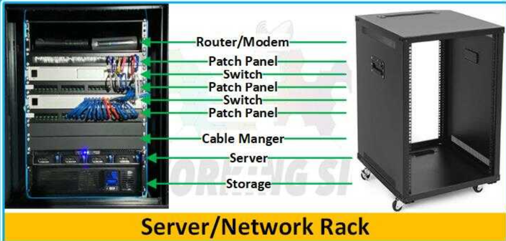
>To see how things works, let’s go through this Simplified graphic. Again, not real, but it’s just so I can explain to you how things work together.

How things connect to each other > Layer 1 OSI. (Blue cable = Cat6 and Purple cable = Fiber Optic cable)
- We got our Switch connected to a bunch of stuff via a Cat 6 cable (Ethernet cable). It’s the main connector used for your typical network devices. And there’s also some phones there, getting access to the network wirelessly (wifi) through the Access Point. Then there’s our L3 Switch (Multilayer Switch) which connects to the Router Via a Fiber Optic cable to get that extra speed out to the gateway (the Router). At last, there is a Firewall between our Router and the Internet, to filter out the network traffic coming into our internal Network.
- The SW connected to the L3 Switch (Distribution Switch) is another L2 Switch (Access Switch) that connects to other devices. And together, all the things Connected to the L3 Switch, forms a LAN, since they all still Local (One location). Don’t worry bout Distribution and Access Switch for now, just putting it here if you wana look up 2 vs 3 Tier Network designs. (Will discuss these stuff more later on for basic Network Architecture Design)
- On the other arm of the Router, we also got another LAN connected to it via Fiber (magically; from a campus somewhere). And this entire thingy, is a WAN (It covers a Wide area. The other LAN is from Disney World! -LAN+LAN=WAN). Also, notice there’s very few things connected to our Router here. That is so that it can forward stuff very fast to and from the internet. (wait, this not something you gotta worry about now LOL) >Anywayyyy, a cool info to know is that, the traffic for most companies now are North-south (stuff that goes In/Out of the Network -to za worldo!) instead of East-West (stuff within the Network -like for Datacenters). That’s why I said earlier that the 10Gps speed of a Cat 6 won’t be a bottleneck anytime soon, with most places not even having a Gigabit Network XD. This North-South traffic is what you want to optimize for when designing Network -hence getting an L3 Switch doing all the internal routing and not the Router (I’ll just leave it at that before I go on another tangent XD)
How it works together (Lvl 1)

- This is just an example of how it works > When you want to search something on your google.com browser. This is how the network traffic flow from your computer to the outside network (internet).
- After the PC get an IP and Network config from your router or DHCP Server/Router.
- The PC should have the Gateway IP from the config (which is the Router’s IP), and it will forward all the traffic for internet to the Gateway, which will send it to the Internet > The Switch has a CAM/MAC Table inside of it, so it knows where to send Stuff with the L3 Switch and the PC it connects to using MAC Address > Then, the L3 Switch has an IP route to the Router (which would be configured as its gateway/default route). Annnd then the Router’s other hand (port) is connected Directly to the ISP, which means it has an IP route to the IS as well, which has Internet Access (In this case, all of that should be auto config since it’s all directly connected). But yeah, more on those “config” on later topics.
- And As you can see, from the inside, the traffic just goes through the Firewall. It’s only when it’s going back that it gets filtered and stuff. (And this one will go through since it was requested from the inside –this why you gotta watch out for Spam emails XD -getting access from the inside is just death XD)
How your internal devices gets sorted out. (little about Subnet + VLAN stuff)
>The separation of network traffic is so that you can manage things better when they’re separate (security, access and whatnot). But for the most part, when troubleshooting Network connection, you want to check to make sure the devices are either in the same VLAN, and/or in the right Network OR they (the devices you’re having issue connecting) can Route (check with pings) to the devices on the other Network/VLAN they need to get access to.
Different VLANs and Different Networks are Routed (Connected) with an L3 Switch (or Router). And so, for different VLANs and Networks (Subnets), you need to check in your L3 Switch (or Router) config, that they actually are allowed (config) to route between each other.
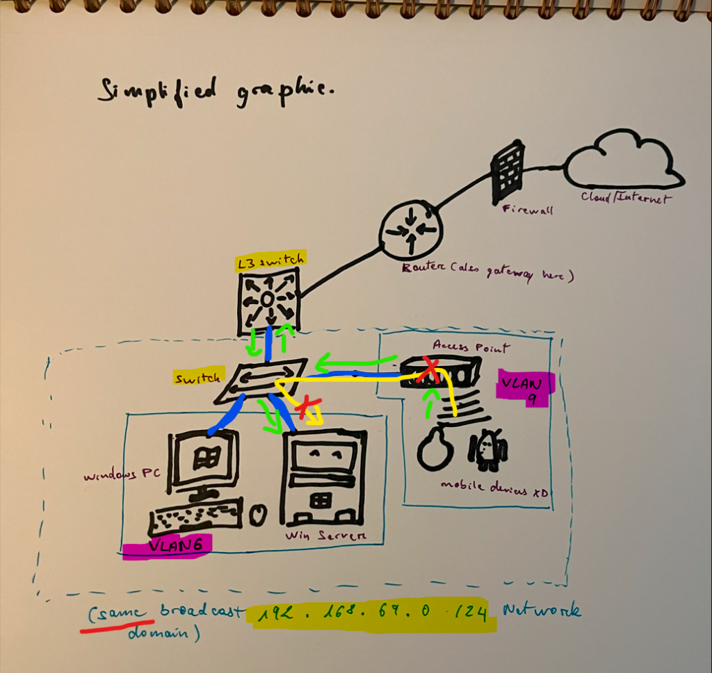
VLAN Separation (Layer 2 OSI)
On the Photo above, the devices in VLAN 9 cannot directly access the Server in VLAN 6, even though they are connected to the same switch > Which means that they are on the same 192.16869.0 /24 Network. That is because as you learned before, you need a Router (or L3 Switch) configured to connect the 2 VLANs. That means that all the traffic that goes to the server from the phones, has to go through the L3 Switch first > then the L3 Switch forward the traffic to the L2 Switch and then server ONLY if it is configured to allow for the VLAN 9 to connect to VLAN6 (You could have more restrictions and Filtering if it was a different Network, but you can add some filtering with VLAN itself as well).
>VLAN separation is nice, but getting stuff on different Subnet (Network) is the better way to manage resources on your Network.
Looking at the Network Layer (Layer 3 OSI)
The Photo Bellow represent the Different Network present on this potato Network Topology. The Different colors represent Different Subnets (Network), and the little black arms represent connection to devices on the same Network, just like the Switch on the Blue Subnet with the various devices inside. This is what the Layer 3 (Network Layer) on the OSI tells you. Whenever you think of Layer 3 > You should be thinking of these different Networks, instead of the Cables Connecting stuff together (Layer 1) or the different VLANs on the L2 Switch (Layer 2).
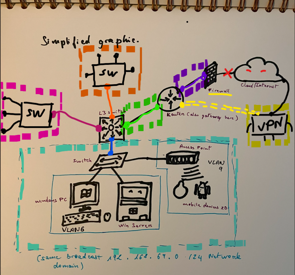
> Every port on a Router or an L3 Switch can have its own Network > Meaning, even the Cables in between the L3 Switch and the Router, has its own Small Network (This is what you could use the /31 Subnet for, with its 2 usable IPs). All These Network (Subnets) needs to have an IP Route between each other, before they can talk to each other > So, you need to config those IP Routes in the L3 Switch and Routers (Layer 3 OSI).
>Note that the VPN, although is actually not physically connected to the Network, still is “directly” connected to the Router. That is thanks to the tunneling done by the Firewall (That means that the Firewall establishes an encrypted and more secure connection through the Internet from the guys working at home, to the Internal Network) > I mean you’ve all seen the VPN ads these days on YouTube lol, it’s the same thing, just for different purpose.
How the Networks Connect to each other (Layer 3 >IPs and Subnets)
When you do the Config for IP/Network Routes (the stuff you need to have Network able to connect to each other). You can plan ahead, so that the resources on each Subnets, only have Connection to the particular Resources they need. That means, you can config some Subnets, to not be able to Route (Connect) to other devices on different Subnets.
>Note that you NEED to have an IP Route TO and FROM the different Subnets you want to connect. For example, to Connect the Orange Subnet to the Blue Subnet, from photo bellow > You need to config an IP Route from Blue to orange, AND another one from Orange to Blue. That way, the Network traffic can be routed between the two Subnets (Networking stuff is always a 2 way deal, gotta make sure both sides are good >You’ll see more of this later with how Network Protocols and services works behind the scenes)
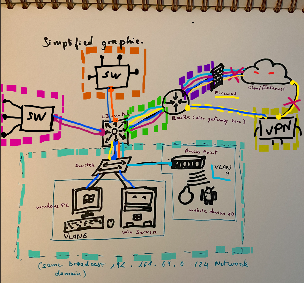
>From the photo above, you can see that Orange Subnet ONLY has access to the Blue Network, and doesn’t have access to the Internet. This Particular Subnet could be a Network assigned to a Dev team working on In-house Applications (for finance stuff or whatever), which you want to keep safer or whatever.
>The Pink Network ONLY has internet access, and isn’t able to Connect to any other internal resources on different Subnets. This could be for your Marketing or Public relations team, that got everything on SharePoint and got all their Network printers on the same floor or whatever.
>Blue Network has access to everything, and actually can be access by everyone as well. This could be a Domain Controller that everyone needs access to.
>Note that the VPN Connection forces the Network Traffic from Yellow Network to go Through the Firewall when it wants to Access Internet, despite the fact that it is actually directly Connected to internet! >This why y’all internet suckkks when you connect to VPN at home for work XD
>You actually can config a different Network on the different VLAN so that they can be managed separately. Like on the Blue Network, VLAN 6 got Dark Blue Network and can access everything, but VLAN 9, with Light Blue Network, can only access Internet.
>You should also be able to see that there are actually quite a bunch of stuff you gotta config, just for the basic potato Network to be able to Route to each other. But you don’t gotta manually config each routes since there are routing protocol that makes it less of a pain (Still a pain, but less… unless you want to be fancy and make a lot of rules and stuff, then it’s A PAINNN).
Going through the Configs > For troubleshooting when things don’t Network together

- To Make things Simpler, I’ll just use this Graphic since it has the actual Network on my virtual lab stuff. But I will briefly mention about different Subnets, to give you an idea on what Layer 3 troubleshooting would look like.
What you need do to make sure this Windows PC can get on the same Domain as the Windows Server!
The way to go about the OSI stack, is >
1- Check the Cables are Connected Properly (Layer 1) >The usual. Y’all know this thing. Check ethernet cable/wifi, power on and off… And it that doesn’t work > PANIC.. JK, you move up the OSI Stack to get that Network to Network again!
2- Check they are connected to the same Switch and on same VLAN (Layer 2) >You would usually skip checking the MAC Table on a Switch and go straight to trying to ping the devices, then you backtrack to this Layer 2 stuff if really needed (If it ever get to the point where you gotta do this, call for support XD)
3- Check the 2 devices have the same Network /Subnet (Layer 3) > You do the IP Subnet thingy from the Subnet Subtopic, or by using the online Calculator if you can’t tell at a glance. You can tell the layer 3 issue is good when you can get successful Ping from one device to another in CMD (sometimes ICMP/aka -the ping protocol, gets blocked in the Firewall settings on a Server, so you could check that as well, but usually this not an issue). Typically, what you gonna be dealing with at work with this, is making sure the remote user/client is connected to the VPN lol. The heavier, Layer 3, Network config troubleshoot will be discussed a bit more later.
4- Skip Layer 4-6 and go straight to Layer 7 Troubleshooting > With DNS and DHCP Services troubleshoot, and/or domain stuff (check previous Topic for more info on this)
>When you got all of those down, then you can domain join the PC XD
Going Through the OSI Stack using the virtual lab setup as an example.
- For our Layer 3 Config > Networking Layer (The different Subnets/Networks stuff). We did the config on an earlier Topic (I think it was Topic #2) to get the server and windows 10 VM to be on the same network (192.168.69.0 /24 Subnet). This is the same as the 2 devices being connected to the same Switch like the picture above > Meaning, no Actual Layer 3 troubleshoot will be needed XD

- Layer 1, 2 and 3 are all linked together since this is a VM > Just like the picture from above with the Windows PC and Server getting Connected to the Same Switch >They are on the same Network (Layer 3 good), they are connected to the same Switch+VLAN (Layer 2 good), there are no cable issue (Layer 1 good).
That means > Even if the computer is not configured with the right DNS or whatever, it should be able to ping the server with its IP (so long as ICMP is not blocked in firewall lol) >anyway, you can see we can ping the server. This confirms that the Windows VM is connected up to Layer 3 on the OSI model.

- If there were more connectivity issues between the two, it will be in the higher layers (Application Layers, and not with Networking). We did a few troubleshooting thingy with those with the DNS and DHCP services.
After everything settle down > You can check to make sure the settings are good > Right Domain, IP from Same Subnet (or Subnet that can ping the other Subnet), and then, the Correct DNS settings, Gateway, etc…)

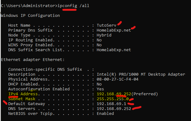
The main takeaway I want you guys to get here is the way to use the OSI Model in your mind when thinking of Network issue/other stuff. So you get the Sequence.
You typically want to start from the bottom, and make your way up. Of course, you don’t always have to do it this way, but this is the sequence you want to check.
- Layer 1 (Physical) > Is the cable connected to the PC properly, or are you connected to the Trusted Wifi?
- Layer 2 (Data Link) > This one, you usually skip first. You wana do layer 3 before checking this since it takes longer to check. (This is when you check the MAC Table of a Switch and make sure the VLANs are connected with a Router somewhere). If it comes to you needing to do this, it’s an issue out of your reach for now XD
- Layer 3 (Network Layer) > This is where you’ll be doing more of the troubleshooting. With Pings and checking if it’s on the correct Subnet, and see if it’s not a duplicate IP, etc…
- I’ll also skip talking about the other layers, since it’s more out of your reach for now. That said, the issue with DNS and DHCP that we troubleshoot before are Layer 7 (Application Layer).
Typically, for many of the simple Network troubleshoot, you’re going to check the cables/connection (Layer 1), and then check to make sure it’s on the same Network/VPN is connected (Layer 3) > and then do a test ping to a server they tryna access (File share Server, or whatever).
If the Ping doesn’t get a reply, it’s a Network issue (or you pinged the wrong stuff!)> (or Either ICMP is blocked in Firewall config on the device) >The 2 devices cannot talk to each other somewhere down the line. Check your Gateway, the subnet, the firewall configs, the weather that day, and maybe even the mood of the computer XD There are a couple things that could block the traffic, but it’s usually just one off the devices getting the wrong IP config (wrong gateway, dns or subnet cus of no VPN), which causes it to not be able to connect to the other one.
When good with troubleshoot, you’ll be moving up and down it > Ping (L3), then maybe cables, and if it not enough, you might need to get back to L2, checking the MAC Table on SW, and then Ping again, And then see why your (Layer 7) Https access to a firewall don’t work XD… Something like that. But still going through the From Bottom UP sequence is the better way at the beginning.
Summary
Well, there is no Summary, cus the last thingy Shoulda put things together… This whole thing is a summary XD lol. But I got a fun Teaser for Future Topics/Tips for those who could use it.
>Just a teaser as well, we will be doing some Cisco config stuff later, but here’s a TIP for those of you already doing Switch/Router/any command line config! > Use ChatGPT. This will save you a lot of time and work.. But yeah, you still gotta do the planning and checking configs and whatever. BUT still this saves you a lot of time (I mean, it’s still faster to copy paste config from a notepad template XD.. but you get the idea.. and it’s great for learning and building configs from scratch).

I never did config with Fortinet syntax but with this, I got some headways :3 huehue (I will still double check with a lab but yeah, it’s a great place to start!) No longer gonna be reading white papers for an hour just to get the basic config for something I know with another OS…

This is beautiful ;-; >Saves me a lot of time for these configs I don’t remember the exact syntax for XD…
I don’t have to fumble with my notes or spend time on a long cisco documentation for something I forgot XD… Just gotta know what you looking for, and double check with official documentation/lab work before deploying. And I mean it’s a tool so you still gotta know how to use it. But man, this makes things a lot simpler. You definitely need to take advantage of it!

>Remember when I said the next Topic was gonna be short XD LOOOOL… *silently crying in ETA on big project I planned out beforehand XD* >But I really wanted all these overview to be in the same place cus I hate having to go through multiple sources for some stuff, and then needing to piece it together to make sense of it. Gotta make sure the thing make sense! > So yeah, pretty noice :3
Anywayyyy Nyght Signing out! (Finally ;-;)